Reducing generator vibration and noise is not only about making a machine quieter. It protects bearings, improves electrical stability, and creates a safer working environment. In 2026, reliable control begins with measurement, not guesswork. Record vibration velocity, sound pressure levels, engine speed, load, and operating temperature before changing components. Small details matter. A loose exhaust bracket can create a sharp metallic rattle, while a poorly supported fuel line may transmit vibration into the frame.
Dr. David A. Bies, co-author of Engineering Noise Control, describes the basic problem clearly: “Noise is unwanted sound.” His principle supports a practical approach to how to reduce generator vibration and noise: control the source, interrupt the transmission path, and protect people from remaining sound. Source control may include engine maintenance, balanced rotating parts, correct alignment, and proper tightening torque. Transmission control often requires resilient mounts, flexible connectors, isolation pads, and a rigid but correctly designed foundation. Acoustic enclosures, silencers, and barriers can reduce airborne noise, but they must preserve ventilation and safe heat removal.
There is no universal fix. A heavy rubber pad may reduce structure-borne vibration, yet worsen movement under an uneven load. An enclosure may lower noise, yet cause overheating if airflow is restricted. That trade-off is easy to underestimate. This guide examines practical methods, inspection points, measurement tools, and installation decisions for modern generator systems. It also recognizes an uncomfortable truth: some “quiet” installations are only quiet from one position. A dependable solution must perform across different loads, distances, and operating conditions.
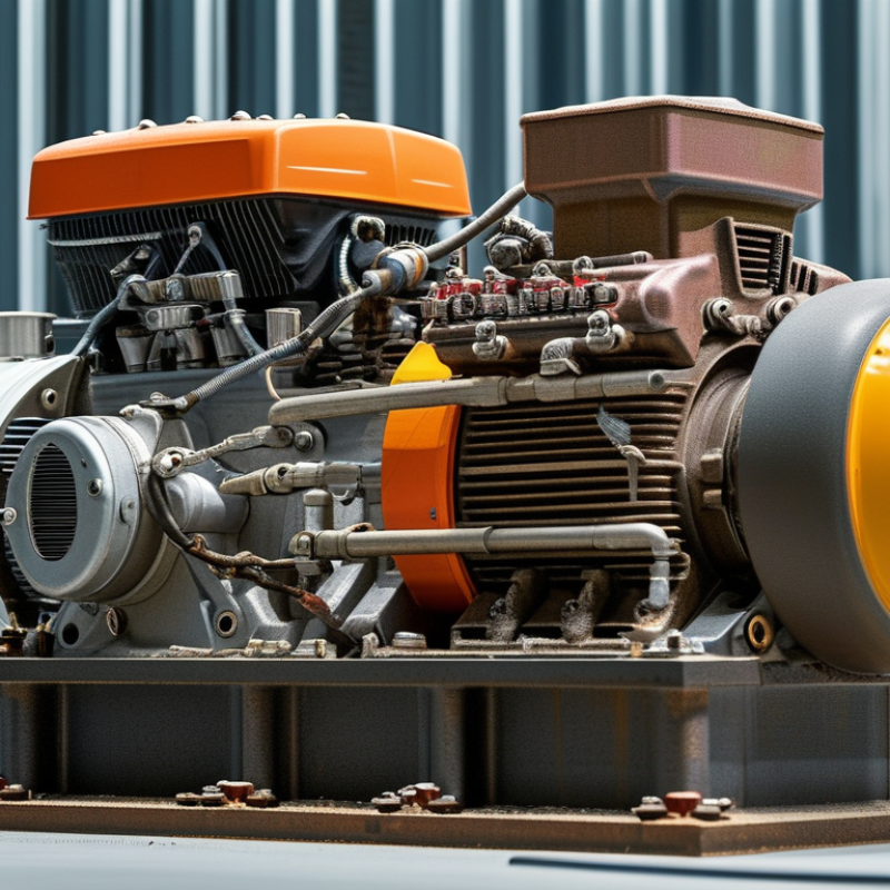
Generator vibration and noise rarely come from one component. The main sources include combustion pulses, rotating imbalance, shaft misalignment, loose fasteners, worn mounts, cooling fans, and exhaust flow. Structural resonance can amplify a moderate engine force into a sharp room-level hum. Start at the source.
A practical inspection should separate airborne noise from structure-borne vibration. A mechanic can use a vibration meter on the frame, alternator housing, and mounting feet. ISO 8528-9:2017 evaluates generating-set vibration through displacement, velocity, or acceleration under defined test conditions. ISO 20816 also emphasizes measurement location and operating speed. Without those details, comparing two readings can be misleading.
Noise measurements need equal discipline. The NIOSH Criteria for a Recommended Standard: Occupational Noise Exposure identifies 85 dBA over eight hours as a recommended exposure limit, using a 3 dB exchange rate. OSHA’s 29 CFR 1910.95 uses a 90 dBA eight-hour permissible limit and a 5 dB exchange rate. These values are worker-protection references, not automatic generator-failure thresholds.
Listen before adjusting. A rattling guard, loose exhaust joint, or stiff mount may create more noise than the engine itself. I would not blame the engine too quickly. Check load level, speed, foundation stiffness, and nearby reflective walls. Thermal expansion can also change alignment after several operating hours, which makes a short test incomplete.
Generator vibration and noise often begin with a poor location, not a faulty machine. Choose a position away from bedrooms, offices, property boundaries, and reflective walls. Keep sufficient clearance for cooling air, exhaust flow, inspection, and safe maintenance. The ground matters. Avoid soft fill, loose gravel, and areas that collect rainwater. A slightly distant generator may create less disturbance than a nearby unit with excellent sound insulation.
A level reinforced-concrete foundation provides stable support and reduces movement. Its size should match the generator’s weight, operating forces, and local ground conditions. Heavy equipment may need an inertia block, especially on weak soil or elevated structures. Install properly selected resilient mounts between the frame and foundation. Do not compress them unevenly. Anchor bolts must hold the equipment without transferring unnecessary vibration into the building.
Use flexible connections for fuel, exhaust, and electrical pathways where appropriate. Rigid pipes can carry vibration into walls and floors. Keep exhaust outlets away from windows and occupied spaces, while maintaining required safety clearances. I have seen installations placed on a thin slab because the surface looked solid. The generator still moved during operation. The mistake was assuming visible concrete meant adequate structural support. A qualified engineer should review the foundation, soil, drainage, and local requirements before installation. After commissioning, measure noise and vibration at nearby occupied areas, then adjust mounts or barriers if readings remain uncomfortable.
| Design Dimension | Recommended Value or Target | Why It Matters | Practical Verification Method |
|---|---|---|---|
| Distance from occupied rooms | Place the generator as far as practical from bedrooms, offices, classrooms, hospitals, and other noise-sensitive areas. Use a separate outdoor plant room where possible. | Airborne noise and structure-borne vibration become easier to control when the source is separated from occupied spaces. | Review the site plan, identify noise-sensitive rooms, and avoid locating the generator directly below or beside them. |
| Distance from property boundaries and openings | Maintain the largest feasible separation from property lines, windows, doors, and outdoor gathering areas. Confirm local noise and fire-code requirements before final placement. | Greater separation reduces sound exposure and limits disturbance to neighboring properties. Regulations vary by location and operating schedule. | Measure the shortest horizontal distance to boundaries and building openings, then compare the layout with applicable local requirements. |
| Ground and drainage conditions | Use firm, well-drained, non-flooding ground with adequate bearing capacity. Keep the foundation above the design flood level where required. | Soft, saturated, or uneven soil can amplify vibration, cause settlement, and transfer movement into nearby structures. | Obtain a geotechnical assessment for large installations or uncertain soil conditions; inspect for standing water and differential settlement. |
| Foundation level and flatness | Provide a rigid, level reinforced-concrete foundation. Follow the generator manufacturer's mounting tolerances; do not rely on loose pavers or an uneven slab. | A level base keeps the engine, alternator, radiator, and flexible connections correctly aligned and prevents rocking. | Check level in both directions with a calibrated level or laser; inspect anchor-bolt positions before placing the set. |
| Foundation mass | For preliminary layout only, a foundation mass of approximately 2 to 3 times the total equipment mass is commonly considered for rigidly mounted sets. Final sizing requires structural and vibration analysis. | A heavier foundation generally lowers dynamic movement, but soil stiffness, excitation frequency, anchor design, and building structure also control performance. | Calculate the operating equipment mass, foundation mass, soil bearing pressure, overturning forces, and dynamic response with a qualified engineer. |
| Foundation dimensions | Extend the concrete pad beyond the equipment footprint sufficiently for anchors, service access, edge distance, and safe maintenance. Use the approved equipment drawing as the controlling dimension. | Adequate edge distance improves anchor performance and reduces the risk of cracking or local slab failure. | Confirm anchor locations, minimum concrete cover, reinforcement, access clearance, and the required service envelope before pouring concrete. |
| Vibration isolation system | Use correctly selected spring isolators or elastomeric mounts when vibration transmission to the building must be limited. Isolation efficiency depends on the operating speed and natural frequency of the system. | A mount that is too stiff may transmit vibration; a mount that is too soft may allow excessive movement during starting, stopping, or fault conditions. | Verify mount capacity, static deflection, natural frequency, seismic restraint, and installed load distribution against the equipment design. |
| Flexible connections | Install flexible sections in exhaust, fuel, cooling, electrical conduit, and other services where the generator is isolated from the structure. | Rigid connections can create vibration bridges and transfer mechanical movement into walls, floors, pipes, and cable trays. | Inspect for sufficient movement allowance, correct alignment, no rigid contact, and compliance with the flexible connector supplier's bending limits. |
| Exhaust system support | Support the exhaust pipe independently from the engine and use a suitable flexible exhaust connector near the engine outlet. | An unsupported or rigid exhaust line can impose loads on the engine and transmit low-frequency vibration through the building. | Confirm that pipe supports carry the pipe weight and thermal movement, while the engine outlet carries only the permitted connector load. |
| Acoustic enclosure or barrier | Use a properly engineered acoustic enclosure or barrier when open-set noise is unacceptable. Do not block required ventilation or radiator airflow. | Enclosures reduce airborne noise, but poor airflow design can increase engine temperature, reduce output, and create additional fan noise. | Verify inlet and outlet airflow, pressure drop, hot-air recirculation, access doors, fire safety, and rated sound performance. |
| Sound level measurement distance | Measure sound consistently at a defined distance, commonly 7 m for generator-set comparisons, and state whether the result is sound pressure or sound power. | Sound readings cannot be compared reliably when distance, background noise, operating load, or measurement method changes. | Use a calibrated sound-level meter, record generator load and weather, and follow the applicable measurement standard or project specification. |
| Distance-related sound reduction | In an unobstructed free field, sound pressure typically decreases by about 6 dB for each doubling of distance. Reflective walls and barriers can change the result. | Location and separation can reduce noise exposure without modifying the generator, although buildings and hard surfaces may cause reflections. | Compare measurements at consistent distances and identify nearby walls, corners, screens, and other reflective surfaces. |
| Avoidance of corners and reflective surfaces | Avoid placing the generator tightly against building corners or between parallel walls unless acoustic modeling accounts for reflections. | Reflected sound can increase local noise levels and create uneven sound distribution around the installation. | Inspect the proposed location for hard vertical surfaces and use barriers with sound-absorbing treatment where permitted and appropriate. |
| Operating load during testing | Evaluate vibration and noise at the normal operating load and at the highest expected continuous load, not only during no-load testing. | Engine excitation, cooling-fan speed, exhaust flow, and structural response can change substantially with load. | Record load percentage, engine speed, vibration velocity, sound level, and ambient conditions for each test point. |
| Vibration acceptance criterion | Set the allowable vibration limit using the generator manufacturer's specification, installation type, and the applicable machinery-vibration standard. Avoid using one universal limit for every set. | Acceptable vibration depends on measurement location, frequency, machine size, mounting arrangement, and whether the value is measured on the machine or structure. | Measure in three directions at defined points using a calibrated vibration meter and compare readings with the approved project criteria. |
| Resonance avoidance | Keep the natural frequency of the foundation and isolation system sufficiently separated from the generator's excitation frequencies. The final separation margin should be established by engineering analysis. | Resonance can greatly amplify vibration even when the generator itself is operating normally. | Review mount deflection and dynamic calculations; investigate any sharp increase in vibration at a particular speed or load. |
| Maintenance clearance | Provide the clearances specified by the equipment and local fire codes around service doors, filters, batteries, radiator airflow paths, and exhaust components. | Restricted access can lead to poor maintenance, while blocked airflow or heat sources can increase noise, vibration, and failure risk. | Verify that doors open fully, lifting paths are available, hot surfaces are protected, and routine service can be completed safely. |
| Post-installation inspection | Inspect anchors, grout, isolators, flexible connectors, exhaust supports, and foundation cracks after commissioning and again after the first period of regular operation. | Loose hardware, settlement, mount displacement, and thermal movement may appear only after the generator has operated under load. | Repeat level, torque, vibration, sound, and visual checks; compare results with the commissioning baseline. |
| Documentation and baseline data | Keep approved foundation drawings, mount calculations, sound readings, vibration readings, operating loads, and maintenance records together. | A documented baseline makes it easier to identify changes before they develop into structural, mechanical, or noise problems. | Record date, location, instrument, calibration status, generator load, weather, measurement points, and corrective actions. |
| Engineering and regulatory review | Have the final location, foundation, fire separation, exhaust, ventilation, acoustic controls, and structural restraints reviewed by qualified professionals. | Generator installations involve mechanical, structural, electrical, fire, environmental, and local noise requirements that cannot be determined by a single dimension alone. | Obtain approval against the equipment drawings, applicable building and fire codes, environmental noise limits, and site-specific engineering requirements. |
Generator vibration often travels through the frame, floor, and exhaust connection. Isolation mounts interrupt this path. Select mounts for the generator’s operating weight, speed, and startup forces. Spring or elastomer mounts can reduce structure-borne vibration when correctly loaded. A mount that looks right can still fail. Uneven loading causes excessive movement and premature wear.
Measure twice. During commissioning, record vibration velocity at the engine frame, mounting feet, and nearby floor. ISO 20816-1:2016 evaluates machine vibration using RMS velocity, but acceptable limits depend on machine type and installation conditions. This matters because a “quiet” generator may still transmit damaging low-frequency energy. Check alignment, bolt torque, soft foot, and exhaust flexibility before changing mount stiffness. Small gaps matter.
Noise control needs more than isolation mounts. Add flexible connectors, acoustic barriers, and a properly sized enclosure where ventilation allows. The World Health Organization’s Environmental Noise Guidelines for the European Region identifies 45 dB Lnight as a recommended outdoor night-time target for road traffic exposure. A generator site may require a different limit, but the figure shows how strict nighttime expectations can be. Measure with calibrated equipment, not a phone alone.
I have seen projects overfocus on airborne noise while ignoring floor vibration. That mistake is common. Review readings after load changes, because vibration can rise sharply near certain operating speeds.
2026 Best Ways to Reduce Generator Vibration and Noise
A properly designed enclosure controls both mechanical and exhaust noise. Start with vibration isolation, not thicker panels. Resilient mounts should match the generator’s operating weight and excitation frequency. Incorrect stiffness can amplify vibration through the base.
Use heavy, sealed panels with mineral-fiber acoustic lining inside the enclosure. Leave no open joints near the engine or alternator. Ventilation openings should use lined acoustic louvers or a baffled airflow path. However, restricted airflow can raise engine temperature and reduce performance. The first enclosure design is often too tight. Measure temperature, pressure drop, and sound after installation.
Exhaust noise needs a correctly sized silencer, flexible connector, and strong support brackets. The silencer should not transfer engine vibration into the enclosure or building structure. NIOSH recommends limiting occupational exposure to 85 dBA over eight hours, using a 3 dB exchange rate, according to its Criteria for a Recommended Standard: Occupational Noise Exposure. A 3 dB increase represents roughly twice the acoustic energy. Small errors matter.
Sound measurements should follow ISO 3744 or ISO 8528-10 practices, with the microphone position recorded clearly. Compare readings before and after enclosure installation. Results can change with distance, reflections, wind, and load. Do not trust one quiet reading. Check the generator at several loads, especially during exhaust surges and startup. A small service door may also become a major sound leak.
Typical sound-reduction ranges for common generator noise-control measures. Values represent practical engineering ranges in dB(A); actual performance depends on generator load, enclosure construction, exhaust design, installation quality, and measurement distance.
Mechanical isolation helps limit structure-borne vibration, while acoustic enclosures and exhaust silencers primarily reduce airborne and exhaust noise. Combining multiple controls generally provides better results than relying on one measure alone.
A quiet generator usually begins with disciplined maintenance, not expensive accessories. Check engine oil, filters, mounts, belts, and exhaust connections before each extended run. Loose bolts can create a sharp metallic rattle. Worn rubber mounts may transfer low vibrations through the floor. Inspect them for cracks, flattening, or oil damage, then replace damaged parts according to the service manual.
Measure the problem before changing the setup. Use a calibrated sound level meter at a fixed distance, such as one metre from the enclosure. Keep the microphone at roughly the operator’s ear height. Record readings at idle and normal load, because noise often changes under electrical demand. A vibration meter or accelerometer can reveal unusual movement on the frame, engine feet, and nearby floor. Record location, load, weather, and operating time with every reading. Small details matter.
Do not trust one reading.
Compare measurements over several days. Rising vibration may indicate imbalance, misalignment, loose hardware, or bearing wear. Stop the unit if movement becomes severe, oil pressure falls, or unfamiliar knocking appears. Keep proper clearance from walls, and never block cooling airflow while reducing sound. Acoustic panels can help, but poorly placed materials may trap heat. I have seen operators chase noise while ignoring a loose exhaust clamp; that mistake is common and expensive. Maintenance records should include each reading, repair, and result, so another technician can verify the improvement.
Common sources include combustion pulses, rotating imbalance, shaft misalignment, loose bolts, worn mounts, fans, and exhaust flow. Listen first.
Use a sound meter for airborne noise and a vibration meter for the frame, housing, mounts, and nearby floor. Measure twice.
Place a calibrated sound meter one metre from the enclosure, near the operator’s ear height. Record the load and operating time.
Generator noise often changes with electrical demand. Compare readings at idle and normal load for a clearer pattern.
Check oil, filters, belts, mounts, fasteners, and exhaust joints. Look for cracked rubber, flattened mounts, oil damage, and loose clamps.
Yes. Nearby reflective walls can amplify sound, while structural resonance can increase a moderate vibration into a strong room hum.
Readings may differ because of measurement location, operating speed, load, weather, or operating time. One reading is not enough.
They can help, but poorly placed materials may trap heat or block cooling airflow. Keep clear ventilation paths.
Stop it if movement becomes severe, oil pressure falls, or unfamiliar knocking appears. Do not keep guessing.
Thermal expansion may change shaft alignment as components heat up. A short test can miss this problem. That matters.
Reducing generator vibration and noise starts with identifying their main sources, including engine imbalance, loose components, exhaust pressure, cooling fans, and poor installation. Choosing a stable location away from occupied areas, using a level and strong foundation, and maintaining adequate clearance can significantly limit vibration transfer and sound reflection. A properly designed base also helps prevent movement and structural damage during operation.
To understand how to reduce generator vibration and noise, install suitable isolation mounts, flexible connectors, and vibration control systems between the generator and surrounding structures. Acoustic enclosures, mufflers, and insulated exhaust systems can further reduce mechanical and exhaust noise without restricting ventilation. Regular maintenance is equally important: check fasteners, bearings, belts, exhaust parts, and mounting hardware, while monitoring sound and vibration levels with appropriate measuring tools. Early detection allows timely adjustments and keeps the generator quieter, smoother, safer, and more reliable.

Gods Power